


本文旨在对扩展板的安装以及扩展板安装后常见问题的解决提供一些详细的指导。
我们将重点介绍安装过程中的电缆连接和安装扩展板后的限位开关故障。
Installation of the extension board.
第一步。Make sure the printer is turned off, installing with electricity on will may cause short circuit and destroy the electronics.请先参考指导视频,完成视频中的前3个步骤,卸下原来的PCB和电缆,然后安装扩展板。
第二步。Insert the small FFC cable one end to the connector on the mainboard, Insert another end to the connector on the extension board, Please notice that ,to insert the cable, ensure the wire exposed side face downwards.


Step 3.将Y轴和Z轴限位开关电缆连接器插入扩展板上相应的彩色连接器。

Step 4.最重要的一步,这一步在视频中被遗漏了,
插入驾驶室限位开关le connector originate from the mainboard (white connector with Y and z limit swithc cable combined).
电缆如下所示,它应该包括并安装在原来的机器,但电缆可能是错误的,当使用扩展电路板。

在插入电缆之前,请检查电缆是否有故障,有些电缆的连接器在出厂时是反向连接的,与扩展PCB一起使用时是有故障的。有缺陷的电缆可以与原来的小PCB板一起工作,但不能与扩展板一起工作,这将导致限位开关无法在Y轴和Z轴上触发。这意味着初始化打印机时,z轴不会停止,即使到达端盖也会继续移动,从而导致初始化失败。
问题的原因是,在释放扩展板之前,小PCB会在限位开关的任何极性上工作。因此,连接器是否正确接线并不重要,但当连接到扩展板时,极性才是重要的。
这就是为什么你可能会发现限位开关可以与原来的印刷电路板,但不与扩展板。对于一些早期买家可能有这个问题,请联系我们的支持团队,以获得一个新的和正确的有线电缆(或您可以简单地反向电线自己)。我们在后来的扩展板包中添加了此电缆,因此在安装扩展板时,请使用新电缆。
确认电缆完好后,将两个2针连接器连接到主板上相应的连接器上,将4针白色连接器连接到扩展板的白色插座上。

第五步,最后的电缆连接如下图所示,不要更换步进电机的电缆并保持在原来的位置并插在主板上,不需要与扩展板连接。

第六步,参照视频完成盖的安装和其他部件的组装。如果您需要使用加热床,请确保加热床FFC电缆需要插入延长板,裸露的电线面朝上。

评论
25条评论
感谢你乔舒亚为这个伟大的教程!
Hey Joshua, how come my package didn't come with a new transfer cable, I used the original Pyz white connector and still works?
@阿诺德,
因为在我们意识到这一问题之前,我们已经将一些内部没有电缆的扩展板发送到欧盟和美国仓库,所以一些早期的买家可能看不到包装中的电缆,但我们后来添加了,未来的买家将看到电缆,如果您没有,请联系我们获取一个。
@乔舒亚,不,我没有。我也没有得到黄色的电源适配器,但我认为它不包括如果你订购220W电源。但为什么我的扩展板和股票电缆一起工作?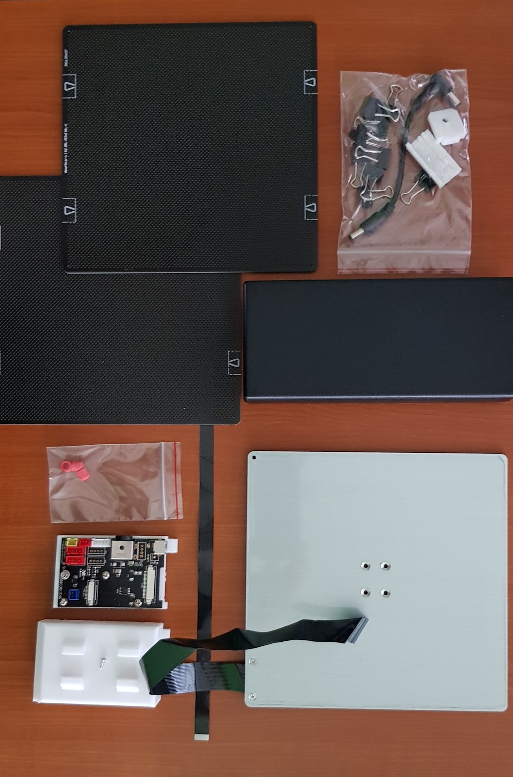
@阿诺德
是的, In the new package we canceled the yellow power adapter ,after a while , we added the limit cable in the package , So the orders during this period ,May no cable inside the package, But the further orders will come with it .
不是所有的,但大部分原来的电缆是可以与延长板,但其中一些不能,然后他们需要更换新的电缆。
@Joshua, I am so lucky then! Everything works :D
@阿诺德,
是啊,如果原来的有线电视能正常工作,你真幸运!
Hi Joshua,
thanks for the more detailed instructions on the extension board. What I'm struggling with is to figure out how to correctly install the heated build plate. The old guide for the beta plate is not applicable/transferable to the new model. How the FFC cable is connected is clear from this guide here.
我还有3个问题:
1我想知道直线轨道轴承座板的新安装。在我的情况下,它是不可能牢固和均匀地安装。要么是有缝隙,要么是角度不对。因为折页处的凹痕(见半紧固螺钉的照片)。需要吗?我的有毛病吗?
Edit: Next photo is with the screw fastened, that results in a tilted bracket:
2. What is the purpose of the printed parts? Where do they go?
3. The cable with two screwable connectors (red/blue) is for an alternative power source, if the Tiertime 220 W power supply is not used, right?
谢谢!
@超人,不要使用半安装在直线导轨块上的支架,我无法想象需要像照片中那样的凹痕。希望它没有改变导块中的螺纹。
如果你有一些不起毛的北京同为lettes, please wipe the sides of the guide-block where it meets the rail and clean-up the dust etc gathering. Also, do you have some really light oil, like sewing-machine oil or hair-trimmer oil that is frequently included for maintenance of said appliances. Not much is needed, but should be added in the side grooves on the guide-block every 5-10 hours of printing. They do say they are self-lubricating, but the grooves on my guide-block become dry frequently.
看起来像是那些印刷零件附着在角托架的顶部(有凹痕),所以它们可能夹在构建板和角托架之间。
我现在就来看看安装指南。
Thanks for looking into it Brent! Will definitely apply your maintenance tips for the guide-block. I have no prior experience with parts like that, so any guidance is welcome :)
Regarding the black screw, not to worry, it's the original one. The photo is a bit misleading. I can fasten the screw more, but that forces the bracket to tilt upwards opposite of the screw because of the dent. (Edit: I updated my post above to include a photo of the tilted state)
Still unsure about the printed parts. The right one on the photo has the same clips as the extension board cover base, that snap into the extruded rods. Maybe it's just supposed to be a cable guide along the z-axis. The one with the hole, still no clue.
这是一张新加热板底部的照片:
编辑:关于三明治理论,我试过几个姿势,但对我来说没什么意义。为了更好的透视,我把照片放进去了。一开始我以为是间隔棒,但太厚了。
I noticed what looks like a nick on the linear rail, on the left towards the end of the rail in the first photo submitted. I recommend to check for any nicks or significant scratches on the rail where the guide-block meets the rails. Any raised scratches and/or nicks in the rail grooves can easily blow-up a bearing because of the tight tolerances between the guide-block and linear rail.
我找不到任何文件可以帮助我,我建议等待从支持你提出的问题,尤其是凹痕!
那个支架肯定有缺陷,我关心的是导向块的螺纹,而不是螺钉/螺栓
Right, it looks like a scratch on the photo, but I just closely inspected the area with a LED flash light and luckily it was just a bit of dust that got into the picture, but thanks for keeping such a close eye!
非常感谢您的关注,非常感谢!我将等待回应,这将文件的加热建设板升级为所有买家。
Can you post a pick of the plastic part with those 4 posts near to the guide-block.
Got ya, with the thread. I was gentle and didn't overdo it and the thread looks perfect still. There is a german saying regarding fastening screws that roughly translates to "after firm comes off". I try to apply that wisdom most times :)
再次感谢,晚安!
Edit: Here the photos of the printed part with the clips:
支架和加热板之间是否没有绝缘层?似乎有太多的热量从加热板传递到导块。去看看从制造商的安全操作温度信息的指导块文件。。。
这是一个伟大的智慧片段!!
好吧,直到下次…祝你旅途愉快!
是的, you're right, the extreme temperatures won't prolong the guide-blocks lifespan.
Wow, yup, there's the relation not seen in separate photos...lol. OK, changing recommendation...try not to push that part into any unsuspecting holes!
K, grab some sleep! Tomorrow it will be...
会的,晚安!
@superhans, the plastic on the left with a hole goes to the rear Y axis guide and secured by one of the screws. The other plastic with an angle is the ribbon cable holder used to secure the ribbon cable, the wide groove is the ribbon cable guide. Both were covered in the older videos that you can find here -https://youtu.be/stUvDT2asPI
谢谢阿诺德,出于某种原因,我一定是完全忽略了视频,虽然我搜索了常见问题/帮助部分,并做了视频搜索,这应该会带来它。奇怪的。。。
Jason Wu also published a additional guide just now:
https://support.tiertime.com/hc/en-us/articles/360023857753-Installation-Guide-of-Heated-Build-Platform-for-Cetus-MK3
拜托sign in留下评论。